
A | B | C | D | E | F | G | H | CH | I | J | K | L | M | N | O | P | Q | R | S | T | U | V | W | X | Y | Z | 0 | 1 | 2 | 3 | 4 | 5 | 6 | 7 | 8 | 9
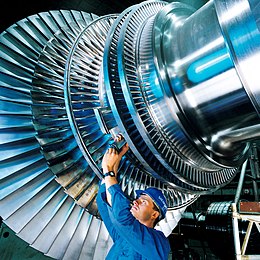
A steam turbine is a machine that extracts thermal energy from pressurized steam and uses it to do mechanical work on a rotating output shaft. Its modern manifestation was invented by Charles Parsons in 1884.[1][2] Fabrication of a modern steam turbine involves advanced metalwork to form high-grade steel alloys into precision parts using technologies that first became available in the 20th century; continued advances in durability and efficiency of steam turbines remains central to the energy economics of the 21st century.
The steam turbine is a form of heat engine that derives much of its improvement in thermodynamic efficiency from the use of multiple stages in the expansion of the steam, which results in a closer approach to the ideal reversible expansion process.
Because the turbine generates rotary motion, it can be coupled to a generator to harness its motion into electricity. Such turbogenerators are the core of thermal power stations which can be fueled by fossil fuels, nuclear fuels, geothermal, or solar energy. About 42% of all electricity generation in the United States in the year 2022 was by use of steam turbines.[3]
Technical challenges include rotor imbalance, vibration, bearing wear, and uneven expansion (various forms of thermal shock). In large installations, even the sturdiest turbine will shake itself apart if operated out of trim.
History
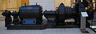
The first device that may be classified as a reaction steam turbine was little more than a toy, the classic Aeolipile, described in the 1st century by Hero of Alexandria in Roman Egypt.[4][5] In 1551, Taqi al-Din in Ottoman Egypt described a steam turbine with the practical application of rotating a spit. Steam turbines were also described by the Italian Giovanni Branca (1629)[6] and John Wilkins in England (1648).[7][8] The devices described by Taqi al-Din and Wilkins are today known as steam jacks. In 1672, an impulse turbine driven small toy car was designed by Ferdinand Verbiest. A more modern version of this car was produced some time in the late 18th century by an unknown German mechanic. In 1775 at Soho James Watt designed a reaction turbine that was put to work there.[9] In 1807, Polikarp Zalesov designed and constructed an impulse turbine, using it for the fire pump operation.[10] In 1827 the Frenchmen Real and Pichon patented and constructed a compound impulse turbine.[11]

The modern steam turbine was invented in 1884 by Charles Parsons, whose first model was connected to a dynamo that generated 7.5 kilowatts (10.1 hp) of electricity.[12] The invention of Parsons' steam turbine made cheap and plentiful electricity possible and revolutionized marine transport and naval warfare.[13] Parsons' design was a reaction type. His patent was licensed and the turbine scaled up shortly after by an American, George Westinghouse. The Parsons turbine also turned out to be easy to scale up. Parsons had the satisfaction of seeing his invention adopted for all major world power stations, and the size of generators had increased from his first 7.5 kilowatts (10.1 hp) set up to units of 50,000 kilowatts (67,000 hp) capacity. Within Parsons' lifetime, the generating capacity of a unit was scaled up by about 10,000 times,[14] and the total output from turbo-generators constructed by his firm C. A. Parsons and Company and by their licensees, for land purposes alone, had exceeded thirty million horse-power.[12]
Other variations of turbines have been developed that work effectively with steam. The de Laval turbine (invented by Gustaf de Laval) accelerated the steam to full speed before running it against a turbine blade. De Laval's impulse turbine is simpler and less expensive and does not need to be pressure-proof. It can operate with any pressure of steam, but is considerably less efficient.[citation needed] Auguste Rateau developed a pressure compounded impulse turbine using the de Laval principle as early as 1896,[15] obtained a US patent in 1903, and applied the turbine to a French torpedo boat in 1904. He taught at the École des mines de Saint-Étienne for a decade until 1897, and later founded a successful company that was incorporated into the Alstom firm after his death. One of the founders of the modern theory of steam and gas turbines was Aurel Stodola, a Slovak physicist and engineer and professor at the Swiss Polytechnical Institute (now ETH) in Zurich. His work Die Dampfturbinen und ihre Aussichten als Wärmekraftmaschinen (English: The Steam Turbine and its prospective use as a Heat Engine) was published in Berlin in 1903. A further book Dampf und Gas-Turbinen (English: Steam and Gas Turbines) was published in 1922.[16]
The Brown-Curtis turbine, an impulse type, which had been originally developed and patented by the U.S. company International Curtis Marine Turbine Company, was developed in the 1900s in conjunction with John Brown & Company. It was used in John Brown-engined merchant ships and warships, including liners and Royal Navy warships.
Manufacturing
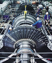
The present day manufacturing industry for steam turbines consists of the following companies:
- WEG (Brazil)
- Harbin Electric, Shanghai Electric, Dongfang Electric (China)
- Doosan Škoda Power (Czech - South Korea)
- Alstom (France)
- Siemens, BTT-Bremer Turbinentechnik GmbH, K&K Turboservice GmbH (Germany)
- BHEL, Larsen & Toubro, Triveni Engineering & Industries (India)
- MAPNA (Iran)
- Ansaldo (Italy)
- Mitsubishi, KwHI, Toshiba, IHI (Japan)
- Silmash, Ural TW, Nevsky Turbine Plant (Nevsky NTW), KTZ, Energomash-Atomenergo, Power Machines, Leningradsky Metallichesky Zavod (Russia)
- Turboatom (Ukraine)
- EDF (France)
- Curtiss-Wright, Elliot Company, GE Vernova, Skinner Power Systems, Baker Hughes, Leonardo DRS, Chart Industries (United States)
- Trillium Flow Technologies (United Kingdom)
Types
Steam turbines are made in a variety of sizes ranging from small <0.75 kW (<1 hp) units (rare) used as mechanical drives for pumps, compressors and other shaft driven equipment, to 1,500 MW (2,000,000 hp) turbines used to generate electricity. There are several classifications for modern steam turbines.
Blade and stage design

Turbine blades are of two basic types, blades and nozzles. Blades move entirely due to the impact of steam on them and their profiles do not converge. This results in a steam velocity drop and essentially no pressure drop as steam moves through the blades. A turbine composed of blades alternating with fixed nozzles is called an impulse turbine, Curtis turbine, Rateau turbine, or Brown-Curtis turbine. Nozzles appear similar to blades, but their profiles converge near the exit. This results in a steam pressure drop and velocity increase as steam moves through the nozzles. Nozzles move due to both the impact of steam on them and the reaction due to the high-velocity steam at the exit. A turbine composed of moving nozzles alternating with fixed nozzles is called a reaction turbine or Parsons turbine.
Except for low-power applications, turbine blades are arranged in multiple stages in series, called compounding, which greatly improves efficiency at low speeds.[18] A reaction stage is a row of fixed nozzles followed by a row of moving nozzles. Multiple reaction stages divide the pressure drop between the steam inlet and exhaust into numerous small drops, resulting in a pressure-compounded turbine. Impulse stages may be either pressure-compounded, velocity-compounded, or pressure-velocity compounded. A pressure-compounded impulse stage is a row of fixed nozzles followed by a row of moving blades, with multiple stages for compounding. This is also known as a Rateau turbine, after its inventor. A velocity-compounded impulse stage (invented by Curtis and also called a "Curtis wheel") is a row of fixed nozzles followed by two or more rows of moving blades alternating with rows of fixed blades. This divides the velocity drop across the stage into several smaller drops.[19] A series of velocity-compounded impulse stages is called a pressure-velocity compounded turbine.
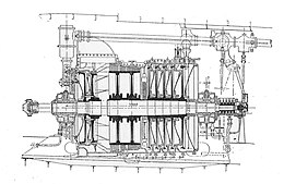
By 1905, when steam turbines were coming into use on fast ships (such as HMS Dreadnought) and in land-based power applications, it had been determined that it was desirable to use one or more Curtis wheels at the beginning of a multi-stage turbine (where the steam pressure is highest), followed by reaction stages. This was more efficient with high-pressure steam due to reduced leakage between the turbine rotor and the casing.[20] This is illustrated in the drawing of the German 1905 AEG marine steam turbine. The steam from the boilers enters from the right at high pressure through a throttle, controlled manually by an operator (in this case a sailor known as the throttleman). It passes through five Curtis wheels and numerous reaction stages (the small blades at the edges of the two large rotors in the middle) before exiting at low pressure, almost certainly to a condenser. The condenser provides a vacuum that maximizes the energy extracted from the steam, and condenses the steam into feedwater to be returned to the boilers. On the left are several additional reaction stages (on two large rotors) that rotate the turbine in reverse for astern operation, with steam admitted by a separate throttle. Since ships are rarely operated in reverse, efficiency is not a priority in astern turbines, so only a few stages are used to save cost.
Blade design challenges
A major challenge facing turbine design was reducing the creep experienced by the blades. Because of the high temperatures and high stresses of operation, steam turbine materials become damaged through these mechanisms. As temperatures are increased in an effort to improve turbine efficiency, creep becomes significant. To limit creep, thermal coatings and superalloys with solid-solution strengthening and grain boundary strengthening are used in blade designs.
Protective coatings are used to reduce the thermal damage and to limit oxidation. These coatings are often stabilized zirconium dioxide-based ceramics. Using a thermal protective coating limits the temperature exposure of the nickel superalloy. This reduces the creep mechanisms experienced in the blade. Oxidation coatings limit efficiency losses caused by a buildup on the outside of the blades, which is especially important in the high-temperature environment.[21]
The nickel-based blades are alloyed with aluminum and titanium to improve strength and creep resistance. The microstructure of these alloys is composed of different regions of composition. A uniform dispersion of the gamma-prime phase – a combination of nickel, aluminum, and titanium – promotes the strength and creep resistance of the blade due to the microstructure.[22]
Refractory elements such as rhenium and ruthenium can be added to the alloy to improve creep strength. The addition of these elements reduces the diffusion of the gamma prime phase, thus preserving the fatigue resistance, strength, and creep resistance.[23]
Steam supply and exhaust conditions

Turbine types include condensing, non-condensing, reheat, extracting and induction.
Condensing turbines
Condensing turbines are most commonly found in electrical power plants. These turbines receive steam from a boiler and exhaust it to a condenser. The exhausted steam is at a pressure well below atmospheric, and is in a partially condensed state, typically of a quality near 90%.
Non-condensing turbines
Non-condensing turbines are most widely used for process steam applications, in which the steam will be used for additional purposes after being exhausted from the turbine. The exhaust pressure is controlled by a regulating valve to suit the needs of the process steam pressure. These are commonly found at refineries, district heating units, pulp and paper plants, and desalination facilities where large amounts of low pressure process steam are needed.
Reheat turbines
Reheat turbines are also used almost exclusively in electrical power plants. In a reheat turbine, steam flow exits from a high-pressure section of the turbine and is returned to the boiler where additional superheat is added. The steam then goes back into an intermediate pressure section of the turbine and continues its expansion. Using reheat in a cycle increases the work output from the turbine and also the expansion reaches conclusion before the steam condenses, thereby minimizing the erosion of the blades in last rows. In most of the cases, maximum number of reheats employed in a cycle is 2 as the cost of super-heating the steam negates the increase in the work output from turbine.
Extracting turbines
Extracting type turbines are common in all applications. In an extracting type turbine, steam is released from various stages of the turbine, and used for industrial process needs or sent to boiler feedwater heaters to improve overall cycle efficiency. Extraction flows may be controlled with a valve, or left uncontrolled. Extracted steam results in a loss of power in the downstream stages of the turbine.
Induction turbines introduce low pressure steam at an intermediate stage to produce additional power.
Casing or shaft arrangements
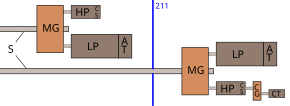
These arrangements include single casing, tandem compound and cross compound turbines. Single casing units are the most basic style where a single casing and shaft are coupled to a generator. Tandem compound are used where two or more casings are directly coupled together to drive a single generator. A cross compound turbine arrangement features two or more shafts not in line driving two or more generators that often operate at different speeds. A cross compound turbine is typically used for many large applications. A typical 1930s-1960s naval installation is illustrated below; this shows high- and low-pressure turbines driving a common reduction gear, with a geared cruising turbine on one high-pressure turbine.
Two-flow rotors

The moving steam imparts both a tangential and axial thrust on the turbine shaft, but the axial thrust in a simple turbine is unopposed. To maintain the correct rotor position and balancing, this force must be counteracted by an opposing force. Thrust bearings can be used for the shaft bearings, the rotor can use dummy pistons, it can be double flow- the steam enters in the middle of the shaft and exits at both ends, or a combination of any of these. In a double flow rotor, the blades in each half face opposite ways, so that the axial forces negate each other but the tangential forces act together. This design of rotor is also called two-flow, double-axial-flow, or double-exhaust. This arrangement is common in low-pressure casings of a compound turbine.[24]
Principle of operation and design
An ideal steam turbine is considered to be an isentropic process, or constant entropy process, in which the entropy of the steam entering the turbine is equal to the entropy of the steam leaving the turbine. No steam turbine is truly isentropic, however, with typical isentropic efficiencies ranging from 20 to 90% based on the application of the turbine. The interior of a turbine comprises several sets of blades or buckets. One set of stationary blades is connected to the casing and one set of rotating blades is connected to the shaft. The sets intermesh with certain minimum clearances, with the size and configuration of sets varying to efficiently exploit the expansion of steam at each stage.
Impulse turbines

An impulse turbine has fixed nozzles that orient the steam flow into high speed jets. These jets contain significant kinetic energy, which is converted into shaft rotation by the bucket-like shaped rotor blades, as the steam jet changes direction. A pressure drop occurs across only the stationary blades, with a net increase in steam velocity across the stage. As the steam flows through the nozzle its pressure falls from inlet pressure to the exit pressure (atmospheric pressure or, more usually, the condenser vacuum). Due to this high ratio of expansion of steam, the steam leaves the nozzle with a very high velocity. The steam leaving the moving blades has a large portion of the maximum velocity of the steam when leaving the nozzle. The loss of energy due to this higher exit velocity is commonly called the carry over velocity or leaving loss.
The law of moment of momentum states that the sum of the moments of external forces acting on a fluid which is temporarily occupying the control volume is equal to the net time change of angular momentum flux through the control volume.
The swirling fluid enters the control volume at radius with tangential velocity and leaves at radius with tangential velocity .
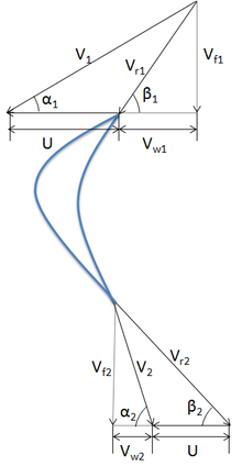
A velocity triangle paves the way for a better understanding of the relationship between the various velocities. In the adjacent figure we have:
- and are the absolute velocities at the inlet and outlet respectively.
- and are the flow velocities at the inlet and outlet respectively.
- and are the swirl velocities at the inlet and outlet respectively, in the moving reference.
- and are the relative velocities at the inlet and outlet respectively.
- is the velocity of the blade.
- is the guide vane angle and is the blade angle.
Then by the law of moment of momentum, the torque on the fluid is given by:
For an impulse steam turbine:
Antropológia
Aplikované vedy
Bibliometria
Dejiny vedy
Encyklopédie
Filozofia vedy
Forenzné vedy
Humanitné vedy
Knižničná veda
Kryogenika
Kryptológia
Kulturológia
Literárna veda
Medzidisciplinárne oblasti
Metódy kvantitatívnej analýzy
Metavedy
Metodika
Text je dostupný za podmienok Creative
Commons Attribution/Share-Alike License 3.0 Unported; prípadne za ďalších
podmienok.
Podrobnejšie informácie nájdete na stránke Podmienky
použitia.
www.astronomia.sk | www.biologia.sk | www.botanika.sk | www.dejiny.sk | www.economy.sk | www.elektrotechnika.sk | www.estetika.sk | www.farmakologia.sk | www.filozofia.sk | Fyzika | www.futurologia.sk | www.genetika.sk | www.chemia.sk | www.lingvistika.sk | www.politologia.sk | www.psychologia.sk | www.sexuologia.sk | www.sociologia.sk | www.veda.sk I www.zoologia.sk


