

A | B | C | D | E | F | G | H | CH | I | J | K | L | M | N | O | P | Q | R | S | T | U | V | W | X | Y | Z | 0 | 1 | 2 | 3 | 4 | 5 | 6 | 7 | 8 | 9


This article duplicates the scope of other articles, specifically Aluminium electrolytic capacitor. (May 2020) |
An electrolytic capacitor is a polarized capacitor whose anode or positive plate is made of a metal that forms an insulating oxide layer through anodization. This oxide layer acts as the dielectric of the capacitor. A solid, liquid, or gel electrolyte covers the surface of this oxide layer, serving as the cathode or negative plate of the capacitor. Because of their very thin dielectric oxide layer and enlarged anode surface, electrolytic capacitors have a much higher capacitance-voltage (CV) product per unit volume than ceramic capacitors or film capacitors, and so can have large capacitance values. There are three families of electrolytic capacitor: aluminium electrolytic capacitors, tantalum electrolytic capacitors, and niobium electrolytic capacitors.
The large capacitance of electrolytic capacitors makes them particularly suitable for passing or bypassing low-frequency signals, and for storing large amounts of energy. They are widely used for decoupling or noise filtering in power supplies and DC link circuits for variable-frequency drives, for coupling signals between amplifier stages, and storing energy as in a flashlamp.
Electrolytic capacitors are polarized components because of their asymmetrical construction and must be operated with a higher potential (i.e., more positive) on the anode than on the cathode at all times. For this reason the polarity is marked on the device housing. Applying a reverse polarity voltage, or a voltage exceeding the maximum rated working voltage of as little as 1 or 1.5 volts, can damage the dielectric causing catastrophic failure of the capacitor itself. Failure of electrolytic capacitors can result in an explosion or fire, potentially causing damage to other components as well as injuries. Bipolar electrolytic capacitors which may be operated with either polarity are also made, using special constructions with two anodes connected in series. A bipolar electrolytic capacitor can also be made by connecting two normal electrolytic capacitors in series, anode to anode or cathode to cathode.
General information
Electrolytic capacitors family tree
As to the basic construction principles of electrolytic capacitors, there are three different types: aluminum, tantalum, and niobium capacitors. Each of these three capacitor families uses non-solid and solid manganese dioxide or solid polymer electrolytes, so a great spread of different combinations of anode material and solid or non-solid electrolytes is available.

Charge principle
Like other conventional capacitors, electrolytic capacitors store the electric energy statically by charge separation in an electric field in the dielectric oxide layer between two electrodes. The non-solid or solid electrolyte in principle is the cathode, which thus forms the second electrode of the capacitor. This and the storage principle distinguish them from electrochemical capacitors or supercapacitors, in which the electrolyte generally is the ionic conductive connection between two electrodes and the storage occurs with statically double-layer capacitance and electrochemical pseudocapacitance.
Basic materials and construction

Electrolytic capacitors use a chemical feature of some special metals, previously called "valve metals", which on contact with a particular electrolyte form a very thin insulating oxide layer on their surface by anodic oxidation which can function as a dielectric. There are three different anode metals in use for electrolytic capacitors:
- Aluminum electrolytic capacitors use a high-purity etched aluminium foil with aluminium oxide as dielectric
- Tantalum electrolytic capacitors use a sintered pellet (“slug”) of high-purity tantalum powder with tantalum pentoxide as dielectric
- Niobium electrolytic capacitors use a sintered "slug" of high-purity niobium or niobium oxide powder with niobium pentoxide as dielectric.
To increase their capacitance per unit volume, all anode materials are either etched or sintered and have a rough surface structure with a much higher surface area compared to a smooth surface of the same area or the same volume. By applying a positive voltage to the above-mentioned anode material in an electrolytic bath an oxide barrier layer with a thickness corresponding to the applied voltage will be formed (formation). This oxide layer acts as dielectric in an electrolytic capacitor. The properties of this oxide layers are given in the following table:
| Anode- material |
Dielectric | Oxide structure |
Relative permittivity |
Breakdown voltage (V/µm) |
Electric layer thickness (nm/V) |
|---|---|---|---|---|---|
| Aluminum | Aluminium oxide Al2O3 | amorphous | 9.6 | 710 | 1.4 |
| crystalline | 11.6…14.2[3] | 800...1000[4] | 1.25...1.0 | ||
| Tantalum | Tantalum pentoxide Ta2O5 | amorphous | 27 | 625 | 1.6 |
| Niobium or Niobium oxide |
Niobium pentoxide Nb2O5 | amorphous | 41 | 400 | 2.5 |
After forming a dielectric oxide on the rough anode structure, a counter electrode has to match the rough insulating oxide surface. This is accomplished by the electrolyte, which acts as the cathode electrode of an electrolytic capacitor. There are many different electrolytes in use. Generally they are distinguished into two species, “non-solid” and “solid” electrolytes. As a liquid medium which has ion conductivity caused by moving ions, non-solid electrolytes can easily fit the rough structures. Solid electrolytes which have electron conductivity can fit the rough structures with the help of special chemical processes like pyrolysis for manganese dioxide or polymerization for conducting polymers.
Comparing the permittivities of the different oxide materials it is seen that tantalum pentoxide has a permittivity approximately three times higher than aluminum oxide. Tantalum electrolytic capacitors of a given CV value theoretically are therefore smaller than aluminium electrolytic capacitors. In practice different safety margins to reach reliable components makes a comparison difficult.
The anodically generated insulating oxide layer is destroyed if the polarity of the applied voltage changes.
Capacitance and volumetric efficiency

Electrolytic capacitors are based on the principle of a "plate capacitor" whose capacitance increases with larger electrode area A, higher dielectric permittivity ε, and thinness of dielectric (d).

The dielectric thickness of electrolytic capacitors is very small, in the range of nanometers per volt. On the other hand, the voltage strengths of these oxide layers are quite high. With this very thin dielectric oxide layer combined with a sufficiently high dielectric strength the electrolytic capacitors can achieve a high volumetric capacitance. This is one reason for the high capacitance values of electrolytic capacitors compared to conventional capacitors.
All etched or sintered anodes have a much higher surface area compared to a smooth surface of the same area or the same volume. That increases the capacitance value, depending on the rated voltage, by a factor of up to 200 for non-solid aluminium electrolytic capacitors as well as for solid tantalum electrolytic capacitors.[5][6][7] The large surface compared to a smooth one is the second reason for the relatively high capacitance values of electrolytic capacitors compared with other capacitor families.
Because the forming voltage defines the oxide layer thickness, the desired voltage rating can be produced very simply. Electrolytic capacitors have high volumetric efficiency, the so-called "CV product", defined as the product of capacitance and voltage divided by volume.
Basic construction of non-solid aluminum electrolytic capacitors
- Basic construction of a non-solid aluminum electrolytic capacitor
-
 Opened winding of an electrolytic capacitor with multiple connected foils
 -
 Closeup cross-section of an aluminium electrolytic capacitor design, showing capacitor anode foil with oxide layer, paper spacer soaked with electrolyte, and cathode foil
 -
 Construction of a typical single-ended aluminium electrolytic capacitor with non-solid electrolyte


Basic construction of solid tantalum electrolytic capacitors
- Construction of a solid tantalum chip capacitor with manganese dioxide electrolyte
-
 The capacitor cell of a tantalum electrolytic capacitor consists of sintered tantalum powder
 -
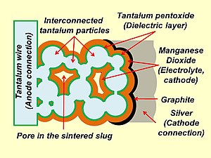 Schematic representation of the structure of a sintered tantalum electrolytic capacitor with solid electrolyte and the cathode contacting layers
 -
 Construction of a typical SMD tantalum electrolytic chip capacitor with solid electrolyte


Types and features of electrolytic capacitors
Comparison of electrolytic capacitor types
Combinations of anode materials for electrolytic capacitors and the electrolytes used have given rise to wide varieties of capacitor types with different properties. An outline of the main characteristics of the different types is shown in the table below.
| Electrolytic capacitor family |
Electrolyte | Capacitance range (µF) |
Max. rated voltage (V) |
Max. temperature (°C) |
|---|---|---|---|---|
| Aluminium- electrolytic capacitor etched foils |
Non-solid, organic electrolyte, e.g. GBL, DMF, DMA, |
0.1:1,000,000 | 550 | 105/125/150 |
| Non-solid, e.g. borax, glycol | 0.1:2,700,000 | 630 | 85/105 | |
| Non-solid, water based | 1:18,000 | 100 | 85/105 | |
| Solid, polymer | 10:1,500 | 25 | 105 | |
| Hybrid, polymer and non-solid | 6.8:1,000 | 125 | 105/125 | |
| Tantalum electrolytic capacitor, sintered anode |
Non-solid, sulfuric acid | 0.1:18,000 | 630 | 125/200 |
| Solid, manganese dioxide | 0.1:3,300 | 125 | 125/150 | |
| Solid, polymer | 10:1,500 | 25 | 105 | |
| Niobium oxide- electrolytic capacitor sintered anode |
Solid, manganese dioxide | 1:1,500 | 10 | 105 |
| Solid, polymer | 4.7:470 | 16 | 105 |
The non-solid or so-called "wet" aluminum electrolytic capacitors were and are the cheapest among all other conventional capacitors. They not only provide the cheapest solutions for high capacitance or voltage values for decoupling and buffering purposes but are also insensitive to low ohmic charging and discharging as well as to low-energy transients. Non-solid electrolytic capacitors can be found in nearly all areas of electronic devices, with the exception of military applications.
Tantalum electrolytic capacitors with solid electrolyte as surface-mountable chip capacitors are mainly used in electronic devices in which little space is available or a low profile is required. They operate reliably over a wide temperature range without large parameter deviations. In military and space applications only tantalum electrolytic capacitors have the necessary approvals.
Niobium electrolytic capacitors are in direct competition with industrial tantalum electrolytic capacitors because niobium is more readily available. Their properties are comparable.
The electrical properties of aluminium, tantalum and niobium electrolytic capacitors have been greatly improved by the polymer electrolyte.
Comparison of electrical parameters
In order to compare the different characteristics of the different electrolytic capacitor types, capacitors with the same dimensions and of similar capacitance and voltage are compared in the following table. In such a comparison the values for ESR and ripple current load are the most important parameters for the use of electrolytic capacitors in modern electronic equipment. The lower the ESR, the higher the ripple current per volume and better functionality of the capacitor in the circuit. However, better electrical parameters come with higher prices.
| Electrolytic capacitor family |
Type 1) | Dimension DxL, WxHxL (mm) |
Max. ESR 100 kHz, 20 °C (mΩ) |
Max. ripple current 85/105 °C (mA) |
Max. leakage current after 2 min. 2) (µA) |
|---|---|---|---|---|---|
| "wet" Al-electrolytic capacitors 1976 3) Ethylene glycol/borax electrolyte |
Valvo, 034, 4.7/40 |
5x11 | 15.000 | 17 | 10 (0.01CV) |
| "wet" Al-electrolytic capacitors, Organic electrolyte |
Vishay, 036 RSP, 100/10 |
5x11 | 1000 | 160 | 10 (0.01CV) |
| "wet" Al-electrolytic capacitors, Ethylene glycol/borax electrolyte |
NCC, SMQ, 100/10 |
5x11 | 900 | 180 | 10 (0.01CV) |
| "wet" Al-electrolytic capacitors, Water-based electrolyte |
Rubycon, ZL, 100/10 |
5x11 | 300 | 250 | 10 (0.01CV) |
| "wet" Al-electrolytic capacitors, SMD Ethylene glycol/borax electrolyte |
NIC, NACY, 220/10 |
6.3x8 | 300 | 300 | 10 (0.01CV) |
| "wet" Al-electrolytic capacitors, SMD Water-based electrolyte |
NIC, NAZJ, 220/16 |
6.3x8 | 160 | 600 | 10 (0.01CV) |
| Solid tantalum electrolytic capacitors MnO2 electrolyte |
Kemet, T494, 330/10 |
7,3x4.3x4.0 | 100 | 1285 | 10 (0.01CV) |
| Solid tantalum electrolytic capacitors Multianode, MnO2 electrolyte |
Kemet, T510, 330/10 |
7.3x4.3x4.0 | 35 | 2500 | 10 (0.01CV) |
| Solid tantalum electrolytic capacitors Polymer electrolyte |
Kemet, T543, 330/10 |
7.3x4.3x4,0 | 10 | 4900 | 100 (0.1CV) |
| Solid tantalum electrolytic capacitors Multianode, polymer |
Kemet, T530, 150/10 |
7.3x4.3x4.0 | 5 | 4970 | 100 (0.1CV) |
| Solid niobium electrolytic capacitors, MnO2 electrolyte |
AVX, NOS, 220/6,3 |
7.3x4.3x4.1 | 80 | 1461 | 20 (0.02CV) |
| Solid niobium electrolytic capacitors, Multianode, MnO2 electrolyte |
AVX, NBM, 220/6.3 |
7.3x4.3x4.1 | 40 | 2561 | 20 (0.02CV) |