

A | B | C | D | E | F | G | H | CH | I | J | K | L | M | N | O | P | Q | R | S | T | U | V | W | X | Y | Z | 0 | 1 | 2 | 3 | 4 | 5 | 6 | 7 | 8 | 9

Diffraction is the interference or bending of waves around the corners of an obstacle or through an aperture into the region of geometrical shadow of the obstacle/aperture. The diffracting object or aperture effectively becomes a secondary source of the propagating wave. Italian scientist Francesco Maria Grimaldi coined the word diffraction and was the first to record accurate observations of the phenomenon in 1660.[1][2]


In classical physics, the diffraction phenomenon is described by the Huygens–Fresnel principle that treats each point in a propagating wavefront as a collection of individual spherical wavelets.[3] The characteristic bending pattern is most pronounced when a wave from a coherent source (such as a laser) encounters a slit/aperture that is comparable in size to its wavelength, as shown in the inserted image. This is due to the addition, or interference, of different points on the wavefront (or, equivalently, each wavelet) that travel by paths of different lengths to the registering surface. If there are multiple, closely spaced openings (e.g., a diffraction grating), a complex pattern of varying intensity can result.
These effects also occur when a light wave travels through a medium with a varying refractive index, or when a sound wave travels through a medium with varying acoustic impedance – all waves diffract,[4] including gravitational waves,[5] water waves, and other electromagnetic waves such as X-rays and radio waves. Furthermore, quantum mechanics also demonstrates that matter possesses wave-like properties and, therefore, undergoes diffraction (which is measurable at subatomic to molecular levels).[6]
The amount of diffraction depends on the size of the gap. Diffraction is greatest when the size of the gap is similar to the wavelength of the wave. In this case, when the waves pass through the gap they become semi-circular.
History

Da Vinci might have observed diffraction in a broadening of the shadow.[7] The effects of diffraction of light were first carefully observed and characterized by Francesco Maria Grimaldi, who also coined the term diffraction, from the Latin diffringere, 'to break into pieces', referring to light breaking up into different directions. The results of Grimaldi's observations were published posthumously in 1665.[8][9][10] Isaac Newton studied these effects and attributed them to inflexion of light rays. James Gregory (1638–1675) observed the diffraction patterns caused by a bird feather, which was effectively the first diffraction grating to be discovered.[11] Thomas Young performed a celebrated experiment in 1803 demonstrating interference from two closely spaced slits.[12] Explaining his results by interference of the waves emanating from the two different slits, he deduced that light must propagate as waves. Augustin-Jean Fresnel did more definitive studies and calculations of diffraction, made public in 1816[13] and 1818,[14] and thereby gave great support to the wave theory of light that had been advanced by Christiaan Huygens[15] and reinvigorated by Young, against Newton's corpuscular theory of light.
Mechanism

In classical physics diffraction arises because of how waves propagate; this is described by the Huygens–Fresnel principle and the principle of superposition of waves. The propagation of a wave can be visualized by considering every particle of the transmitted medium on a wavefront as a point source for a secondary spherical wave. The wave displacement at any subsequent point is the sum of these secondary waves. When waves are added together, their sum is determined by the relative phases as well as the amplitudes of the individual waves so that the summed amplitude of the waves can have any value between zero and the sum of the individual amplitudes. Hence, diffraction patterns usually have a series of maxima and minima.
In the modern quantum mechanical understanding of light propagation through a slit (or slits) every photon is described by its wavefunction that determines the probability distribution for the photon: the light and dark bands are the areas where the photons are more or less likely to be detected. The wavefunction is determined by the physical surroundings such as slit geometry, screen distance, and initial conditions when the photon is created. The wave nature of individual photons (as opposed to wave properties only arising from the interactions between multitudes of photons) was implied by a low-intensity double-slit experiment first performed by G. I. Taylor in 1909. The quantum approach has some striking similarities to the Huygens-Fresnel principle; based on that principle, as light travels through slits and boundaries, secondary point light sources are created near or along these obstacles, and the resulting diffraction pattern is going to be the intensity profile based on the collective interference of all these light sources that have different optical paths. In the quantum formalism, that is similar to considering the limited regions around the slits and boundaries from which photons are more likely to originate, and calculating the probability distribution (that is proportional to the resulting intensity of classical formalism).
There are various analytical models which allow the diffracted field to be calculated, including the Kirchhoff diffraction equation (derived from the wave equation),[16] the Fraunhofer diffraction approximation of the Kirchhoff equation (applicable to the far field), the Fresnel diffraction approximation (applicable to the near field) and the Feynman path integral formulation. Most configurations cannot be solved analytically, but can yield numerical solutions through finite element and boundary element methods.
It is possible to obtain a qualitative understanding of many diffraction phenomena by considering how the relative phases of the individual secondary wave sources vary, and, in particular, the conditions in which the phase difference equals half a cycle in which case waves will cancel one another out.
The simplest descriptions of diffraction are those in which the situation can be reduced to a two-dimensional problem. For water waves, this is already the case; water waves propagate only on the surface of the water. For light, we can often neglect one direction if the diffracting object extends in that direction over a distance far greater than the wavelength. In the case of light shining through small circular holes, we will have to take into account the full three-dimensional nature of the problem.
-
 Computer-generated intensity pattern formed on a screen by diffraction from a square aperture
 -
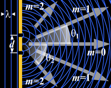 Generation of an interference pattern from two-slit diffraction
 -
 Computational model of an interference pattern from two-slit diffraction
 -
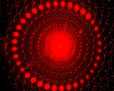 Optical diffraction pattern (laser, analogous to X-ray crystallography)
 -
 Colors seen in a spider web are partially due to diffraction, according to some analyses.[17]


,_(analogous_to_X-ray_crystallography).JPG)

Examples
The effects of diffraction are often seen in everyday life. The most striking examples of diffraction are those that involve light; for example, the closely spaced tracks on a CD or DVD act as a diffraction grating to form the familiar rainbow pattern seen when looking at a disc.


This principle can be extended to engineer a grating with a structure such that it will produce any diffraction pattern desired; the hologram on a credit card is an example.
Diffraction in the atmosphere by small particles can cause a bright ring to be visible around a bright light source like the sun or the moon.

A shadow of a solid object, using light from a compact source, shows small fringes near its edges.

Diffraction spikes are diffraction patterns caused due to non-circular aperture in camera or support struts in telescope; In normal vision, diffraction through eyelashes may produce such spikes.


The speckle pattern which is observed when laser light falls on an optically rough surface is also a diffraction phenomenon. When deli meat appears to be iridescent, that is diffraction off the meat fibers.[18] All these effects are a consequence of the fact that light propagates as a wave.
Diffraction can occur with any kind of wave. Ocean waves diffract around jetties and other obstacles.

Sound waves can diffract around objects, which is why one can still hear someone calling even when hiding behind a tree.[19]
Diffraction can also be a concern in some technical applications; it sets a fundamental limit to the resolution of a camera, telescope, or microscope.
Other examples of diffraction are considered below.
Single-slit diffraction


.svg)
A long slit of infinitesimal width which is illuminated by light diffracts the light into a series of circular waves and the wavefront which emerges from the slit is a cylindrical wave of uniform intensity, in accordance with the Huygens–Fresnel principle.
An illuminated slit that is wider than a wavelength produces interference effects in the space downstream of the slit. Assuming that the slit behaves as though it has a large number of point sources spaced evenly across the width of the slit interference effects can be calculated. The analysis of this system is simplified if we consider light of a single wavelength. If the incident light is coherent, these sources all have the same phase. Light incident at a given point in the space downstream of the slit is made up of contributions from each of these point sources and if the relative phases of these contributions vary by or more, we may expect to find minima and maxima in the diffracted light. Such phase differences are caused by differences in the path lengths over which contributing rays reach the point from the slit.

We can find the angle at which a first minimum is obtained in the diffracted light by the following reasoning. The light from a source located at the top edge of the slit interferes destructively with a source located at the middle of the slit, when the path difference between them is equal to . Similarly, the source just below the top of the slit will interfere destructively with the source located just below the middle of the slit at the same angle. We can continue this reasoning along the entire height of the slit to conclude that the condition for destructive interference for the entire slit is the same as the condition for destructive interference between two narrow slits a distance apart that is half the width of the slit. The path difference is approximately so that the minimum intensity occurs at an angle given by


A similar argument can be used to show that if we imagine the slit to be divided into four, six, eight parts, etc., minima are obtained at angles given by


There is no such simple argument to enable us to find the maxima of the diffraction pattern. The intensity profile can be calculated using the Fraunhofer diffraction equation as


This analysis applies only to the far field (Fraunhofer diffraction), that is, at a distance much larger than the width of the slit.
From the intensity profile above, if , the intensity will have little dependency on , hence the wavefront emerging from the slit would resemble a cylindrical wave with azimuthal symmetry; If , only would have appreciable intensity, hence the wavefront emerging from the slit would resemble that of geometrical optics.


When the incident angle of the light onto the slit is non-zero (which causes a change in the path length), the intensity profile in the Fraunhofer regime (i.e. far field) becomes:


The choice of plus/minus sign depends on the definition of the incident angle .


Diffraction grating
A diffraction grating is an optical component with a regular pattern. The form of the light diffracted by a grating depends on the structure of the elements and the number of elements present, but all gratings have intensity maxima at angles θm which are given by the grating equation


The light diffracted by a grating is found by summing the light diffracted from each of the elements, and is essentially a convolution of diffraction and interference patterns.
The figure shows the light diffracted by 2-element and 5-element gratings where the grating spacings are the same; it can be seen that the maxima are in the same position, but the detailed structures of the intensities are different.


Circular aperture
The far-field diffraction of a plane wave incident on a circular aperture is often referred to as the Airy disk. The variation in intensity with angle is given by
Antropológia
Aplikované vedy
Bibliometria
Dejiny vedy
Encyklopédie
Filozofia vedy
Forenzné vedy
Humanitné vedy
Knižničná veda
Kryogenika
Kryptológia
Kulturológia
Literárna veda
Medzidisciplinárne oblasti
Metódy kvantitatívnej analýzy
Metavedy
Metodika
Text je dostupný za podmienok Creative
Commons Attribution/Share-Alike License 3.0 Unported; prípadne za ďalších
podmienok.
Podrobnejšie informácie nájdete na stránke Podmienky
použitia.
www.astronomia.sk | www.biologia.sk | www.botanika.sk | www.dejiny.sk | www.economy.sk | www.elektrotechnika.sk | www.estetika.sk | www.farmakologia.sk | www.filozofia.sk | Fyzika | www.futurologia.sk | www.genetika.sk | www.chemia.sk | www.lingvistika.sk | www.politologia.sk | www.psychologia.sk | www.sexuologia.sk | www.sociologia.sk | www.veda.sk I www.zoologia.sk