A | B | C | D | E | F | G | H | CH | I | J | K | L | M | N | O | P | Q | R | S | T | U | V | W | X | Y | Z | 0 | 1 | 2 | 3 | 4 | 5 | 6 | 7 | 8 | 9


In radio and telecommunications a dipole antenna or doublet[1] is one of the two simplest and most widely-used types of antenna; the other is the monopole.[2][3][full citation needed] The dipole is any one of a class of antennas producing a radiation pattern approximating that of an elementary electric dipole with a radiating structure supporting a line current so energized that the current has only one node at each far end.[a] A dipole antenna commonly consists of two identical conductive elements[5] such as metal wires or rods.[2][6][7](p 3) The driving current from the transmitter is applied, or for receiving antennas the output signal to the receiver is taken, between the two halves of the antenna. Each side of the feedline to the transmitter or receiver is connected to one of the conductors. This contrasts with a monopole antenna, which consists of a single rod or conductor with one side of the feedline connected to it, and the other side connected to some type of ground.[7] A common example of a dipole is the "rabbit ears" television antenna found on broadcast television sets. All dipoles are electrically equivalent to two monopoles mounted end-to-end and fed with opposite phases, with the ground plane between them made "virtual" by the opposing monopole.
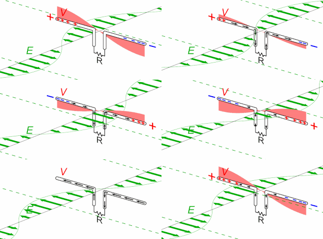
The dipole is the simplest type of antenna from a theoretical point of view.[1] Most commonly it consists of two conductors of equal length oriented end-to-end with the feedline connected between them.[8][9] Dipoles are frequently used as resonant antennas. If the feedpoint of such an antenna is shorted, then it will be able to resonate at a particular frequency, just like a guitar string that is plucked. Using the antenna at around that frequency is advantageous in terms of feedpoint impedance (and thus standing wave ratio), so its length is determined by the intended wavelength (or frequency) of operation.[2] The most commonly used is the center-fed half-wave dipole which is just under a half-wavelength long. The radiation pattern of the half-wave dipole is maximum perpendicular to the conductor, falling to zero in the axial direction, thus implementing an omnidirectional antenna if installed vertically, or (more commonly) a weakly directional antenna if horizontal.[10]
Although they may be used as standalone low-gain antennas, dipoles are also employed as driven elements in more complex antenna designs[2][5] such as the Yagi antenna and driven arrays. Dipole antennas (or such designs derived from them, including the monopole) are used to feed more elaborate directional antennas such as a horn antenna, parabolic reflector, or corner reflector. Engineers analyze vertical (or other monopole) antennas on the basis of dipole antennas of which they are one half.
History
German physicist Heinrich Hertz first demonstrated the existence of radio waves in 1887 using what we now know as a dipole antenna (with capacitative end-loading). On the other hand, Guglielmo Marconi empirically found that he could just ground the transmitter (or one side of a transmission line, if used) dispensing with one half of the antenna, thus realizing the vertical or monopole antenna.[7](p 3) For the low frequencies Marconi employed to achieve long-distance communications, this form was more practical; when radio moved to higher frequencies (especially VHF transmissions for FM radio and TV) it was advantageous for these much smaller antennas to be entirely atop a tower thus requiring a dipole antenna or one of its variations.
In the early days of radio, the thus-named Marconi antenna (monopole) and the doublet (dipole) were seen as distinct inventions. Now, however, the "monopole" antenna is understood as a special case of a dipole which has a virtual element "underground".
Dipole variations
Short dipole
A short dipole is a dipole formed by two conductors with a total length ℓ substantially less than a half wavelength ( 1/ 2 λ ). Short dipoles are sometimes used in applications where a full half-wave dipole would be too large. They can be analyzed easily using the results obtained below for the Hertzian dipole, a fictitious entity. Being shorter than a resonant antenna (half wavelength long) its feedpoint impedance includes a large capacitive reactance requiring a loading coil or other matching network in order to be practical, especially as a transmitting antenna.
To find the far-field electric and magnetic fields generated by a short dipole we use the result shown below for the Hertzian dipole (an infinitesimal current element) at a distance r from the current and at an angle θ to the direction of the current, as being:[11](p 213)
where the radiator consists of a current of over a short length ℓ and in electronics replaces the customary mathematical symbol i for the "square root of −1". ω is the radian frequency () and k is the wavenumber (). ζ0 is the impedance of free space (), which is the ratio of a free space plane wave's electric to magnetic field strength.

The feedpoint is usually at the center of the dipole as shown in the diagram. The current along dipole arms are approximately described as proportional to where z is the distance to the end of the arm. In the case of a short dipole, that is essentially a linear drop from at the feedpoint to zero at the end. Therefore, this is comparable to a Hertzian dipole with an effective current Ih equal to the average current over the conductor, so With that substitution, the above equations closely approximate the fields generated by a short dipole fed by current
From the fields calculated above, one can find the radiated flux (power per unit area) at any point as the magnitude of the real part of the Poynting vector, S, which is given by With E and H being at right angles and in phase, there is no imaginary part and is simply equal to with the phase factors (the exponentials) cancelling out leaving:
Antropológia
Aplikované vedy
Bibliometria
Dejiny vedy
Encyklopédie
Filozofia vedy
Forenzné vedy
Humanitné vedy
Knižničná veda
Kryogenika
Kryptológia
Kulturológia
Literárna veda
Medzidisciplinárne oblasti
Metódy kvantitatívnej analýzy
Metavedy
Metodika
Text je dostupný za podmienok Creative
Commons Attribution/Share-Alike License 3.0 Unported; prípadne za ďalších
podmienok.
Podrobnejšie informácie nájdete na stránke Podmienky
použitia.
www.astronomia.sk | www.biologia.sk | www.botanika.sk | www.dejiny.sk | www.economy.sk | www.elektrotechnika.sk | www.estetika.sk | www.farmakologia.sk | www.filozofia.sk | Fyzika | www.futurologia.sk | www.genetika.sk | www.chemia.sk | www.lingvistika.sk | www.politologia.sk | www.psychologia.sk | www.sexuologia.sk | www.sociologia.sk | www.veda.sk I www.zoologia.sk


