A | B | C | D | E | F | G | H | CH | I | J | K | L | M | N | O | P | Q | R | S | T | U | V | W | X | Y | Z | 0 | 1 | 2 | 3 | 4 | 5 | 6 | 7 | 8 | 9
This article needs additional citations for verification. (March 2023) |

| Articles about |
| Electromagnetism |
|---|
 |
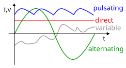
Alternating current (AC) is an electric current that periodically reverses direction and changes its magnitude continuously with time, in contrast to direct current (DC), which flows only in one direction. Alternating current is the form in which electric power is delivered to businesses and residences, and it is the form of electrical energy that consumers typically use when they plug kitchen appliances, televisions, fans and electric lamps into a wall socket. The abbreviations AC and DC are often used to mean simply alternating and direct, respectively, as when they modify current or voltage.[1][2]
The usual waveform of alternating current in most electric power circuits is a sine wave, whose positive half-period corresponds with positive direction of the current and vice versa (the full period is called a cycle). In certain applications, like guitar amplifiers, different waveforms are used, such as triangular waves or square waves. Audio and radio signals carried on electrical wires are also examples of alternating current. These types of alternating current carry information such as sound (audio) or images (video) sometimes carried by modulation of an AC carrier signal. These currents typically alternate at higher frequencies than those used in power transmission.
Transmission, distribution, and domestic power supply

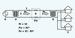
Electrical energy is distributed as alternating current because AC voltage may be increased or decreased with a transformer. This allows the power to be transmitted through power lines efficiently at high voltage, which reduces the energy lost as heat due to resistance of the wire, and transformed to a lower, safer voltage for use. Use of a higher voltage leads to significantly more efficient transmission of power. The power losses () in the wire are a product of the square of the current ( I ) and the resistance (R) of the wire, described by the formula:
This means that when transmitting a fixed power on a given wire, if the current is halved (i.e. the voltage is doubled), the power loss due to the wire's resistance will be reduced to one quarter.
The power transmitted is equal to the product of the current and the voltage (assuming no phase difference); that is,
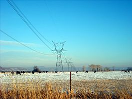
Consequently, power transmitted at a higher voltage requires less loss-producing current than for the same power at a lower voltage. Power is often transmitted at hundreds of kilovolts on pylons, and transformed down to tens of kilovolts to be transmitted on lower level lines, and finally transformed down to 100 V – 240 V for domestic use.

High voltages have disadvantages, such as the increased insulation required, and generally increased difficulty in their safe handling. In a power plant, energy is generated at a convenient voltage for the design of a generator, and then stepped up to a high voltage for transmission. Near the loads, the transmission voltage is stepped down to the voltages used by equipment. Consumer voltages vary somewhat depending on the country and size of load, but generally motors and lighting are built to use up to a few hundred volts between phases. The voltage delivered to equipment such as lighting and motor loads is standardized, with an allowable range of voltage over which equipment is expected to operate. Standard power utilization voltages and percentage tolerance vary in the different mains power systems found in the world.
High-voltage direct-current (HVDC) electric power transmission systems have become more viable as technology has provided efficient means of changing the voltage of DC power. Transmission with high voltage direct current was not feasible in the early days of electric power transmission, as there was then no economically viable way to step the voltage of DC down for end user applications such as lighting incandescent bulbs.
Three-phase electrical generation is very common. The simplest way is to use three separate coils in the generator stator, physically offset by an angle of 120° (one-third of a complete 360° phase) to each other. Three current waveforms are produced that are equal in magnitude and 120° out of phase to each other. If coils are added opposite to these (60° spacing), they generate the same phases with reverse polarity and so can be simply wired together. In practice, higher "pole orders" are commonly used. For example, a 12-pole machine would have 36 coils (10° spacing). The advantage is that lower rotational speeds can be used to generate the same frequency. For example, a 2-pole machine running at 3600 rpm and a 12-pole machine running at 600 rpm produce the same frequency; the lower speed is preferable for larger machines. If the load on a three-phase system is balanced equally among the phases, no current flows through the neutral point. Even in the worst-case unbalanced (linear) load, the neutral current will not exceed the highest of the phase currents. Non-linear loads (e.g. the switch-mode power supplies widely used) may require an oversized neutral bus and neutral conductor in the upstream distribution panel to handle harmonics. Harmonics can cause neutral conductor current levels to exceed that of one or all phase conductors.
For three-phase at utilization voltages a four-wire system is often used. When stepping down three-phase, a transformer with a Delta (3-wire) primary and a Star (4-wire, center-earthed) secondary is often used so there is no need for a neutral on the supply side. For smaller customers (just how small varies by country and age of the installation) only a single phase and neutral, or two phases and neutral, are taken to the property. For larger installations all three phases and neutral are taken to the main distribution panel. From the three-phase main panel, both single and three-phase circuits may lead off. Three-wire single-phase systems, with a single center-tapped transformer giving two live conductors, is a common distribution scheme for residential and small commercial buildings in North America. This arrangement is sometimes incorrectly referred to as "two phase". A similar method is used for a different reason on construction sites in the UK. Small power tools and lighting are supposed to be supplied by a local center-tapped transformer with a voltage of 55 V between each power conductor and earth. This significantly reduces the risk of electric shock in the event that one of the live conductors becomes exposed through an equipment fault whilst still allowing a reasonable voltage of 110 V between the two conductors for running the tools.
A third wire, called the bond (or earth) wire, is often connected between non-current-carrying metal enclosures and earth ground. This conductor provides protection from electric shock due to accidental contact of circuit conductors with the metal chassis of portable appliances and tools. Bonding all non-current-carrying metal parts into one complete system ensures there is always a low electrical impedance path to ground sufficient to carry any fault current for as long as it takes for the system to clear the fault. This low impedance path allows the maximum amount of fault current, causing the overcurrent protection device (breakers, fuses) to trip or burn out as quickly as possible, bringing the electrical system to a safe state. All bond wires are bonded to ground at the main service panel, as is the neutral/identified conductor if present.
AC power supply frequencies
The frequency of the electrical system varies by country and sometimes within a country; most electric power is generated at either 50 or 60 Hertz. Some countries have a mixture of 50 Hz and 60 Hz supplies, notably electricity power transmission in Japan. A low frequency eases the design of electric motors, particularly for hoisting, crushing and rolling applications, and commutator-type traction motors for applications such as railways. However, low frequency also causes noticeable flicker in arc lamps and incandescent light bulbs. The use of lower frequencies also provided the advantage of lower transmission losses, which are proportional to frequency. The original Niagara Falls generators were built to produce 25 Hz power, as a compromise between low frequency for traction and heavy induction motors, while still allowing incandescent lighting to operate (although with noticeable flicker). Most of the 25 Hz residential and commercial customers for Niagara Falls power were converted to 60 Hz by the late 1950s, although some[which?] 25 Hz industrial customers still existed as of the start of the 21st century. 16.7 Hz power (formerly 16 2/3 Hz) is still used in some European rail systems, such as in Austria, Germany, Norway, Sweden and Switzerland. Off-shore, military, textile industry, marine, aircraft, and spacecraft applications sometimes use 400 Hz, for benefits of reduced weight of apparatus or higher motor speeds. Computer mainframe systems were often powered by 400 Hz or 415 Hz for benefits of ripple reduction while using smaller internal AC to DC conversion units.[citation needed]
Effects at high frequencies
A direct current flows uniformly throughout the cross-section of a homogeneous electrically conducting wire. An alternating current of any frequency is forced away from the wire's center, toward its outer surface. This is because an alternating current (which is the result of the acceleration of electric charge) creates electromagnetic waves (a phenomenon known as electromagnetic radiation). Electric conductors are not conducive to electromagnetic waves (a perfect electric conductor prohibits all electromagnetic waves within its boundary), so a wire that is made of a non-perfect conductor (a conductor with finite, rather than infinite, electrical conductivity) pushes the alternating current, along with their associated electromagnetic fields, away from the wire's center. The phenomenon of alternating current being pushed away from the center of the conductor is called skin effect, and a direct current does not exhibit this effect, since a direct current does not create electromagnetic waves.
At very high frequencies, the current no longer flows in the wire, but effectively flows on the surface of the wire, within a thickness of a few skin depths. The skin depth is the thickness at which the current density is reduced by 63%. Even at relatively low frequencies used for power transmission (50 Hz – 60 Hz), non-uniform distribution of current still occurs in sufficiently thick conductors. For example, the skin depth of a copper conductor is approximately 8.57 mm at 60 Hz, so high current conductors are usually hollow to reduce their mass and cost. This tendency of alternating current to flow predominantly in the periphery of conductors reduces the effective cross-section of the conductor. This increases the effective AC resistance of the conductor, since resistance is inversely proportional to the cross-sectional area. A conductor's AC resistance is higher than its DC resistance, causing a higher energy loss due to ohmic heating (also called I2R loss).
Techniques for reducing AC resistance
For low to medium frequencies, conductors can be divided into stranded wires, each insulated from the others, with the relative positions of individual strands specially arranged within the conductor bundle. Wire constructed using this technique is called Litz wire. This measure helps to partially mitigate skin effect by forcing more equal current throughout the total cross section of the stranded conductors. Litz wire is used for making high-Q inductors, reducing losses in flexible conductors carrying very high currents at lower frequencies, and in the windings of devices carrying higher radio frequency current (up to hundreds of kilohertz), such as switch-mode power supplies and radio frequency transformers.
Techniques for reducing radiation loss
As written above, an alternating current is made of electric charge under periodic acceleration, which causes radiation of electromagnetic waves. Energy that is radiated is lost. Depending on the frequency, different techniques are used to minimize the loss due to radiation.
Twisted pairs
At frequencies up to about 1 GHz, pairs of wires are twisted together in a cable, forming a twisted pair. This reduces losses from electromagnetic radiation and inductive coupling. A twisted pair must be used with a balanced signalling system, so that the two wires carry equal but opposite currents. Each wire in a twisted pair radiates a signal, but it is effectively cancelled by radiation from the other wire, resulting in almost no radiation loss.
Coaxial cables
Coaxial cables are commonly used at audio frequencies and above for convenience. A coaxial cable has a conductive wire inside a conductive tube, separated by a dielectric layer. The current flowing on the surface of the inner conductor is equal and opposite to the current flowing on the inner surface of the outer tube. The electromagnetic field is thus completely contained within the tube, and (ideally) no energy is lost to radiation or coupling outside the tube. Coaxial cables have acceptably small losses for frequencies up to about 5 GHz. For microwave frequencies greater than 5 GHz, the losses (due mainly to the dielectric separating the inner and outer tubes being a non-ideal insulator) become too large, making waveguides a more efficient medium for transmitting energy. Coaxial cables often use a perforated dielectric layer to separate the inner and outer conductors in order to minimize the power dissipated by the dielectric.
Waveguides
Waveguides are similar to coaxial cables, as both consist of tubes, with the biggest difference being that waveguides have no inner conductor. Waveguides can have any arbitrary cross section, but rectangular cross sections are the most common. Because waveguides do not have an inner conductor to carry a return current, waveguides cannot deliver energy by means of an electric current, but rather by means of a guided electromagnetic field. Although surface currents do flow on the inner walls of the waveguides, those surface currents do not carry power. Power is carried by the guided electromagnetic fields. The surface currents are set up by the guided electromagnetic fields and have the effect of keeping the fields inside the waveguide and preventing leakage of the fields to the space outside the waveguide. Waveguides have dimensions comparable to the wavelength of the alternating current to be transmitted, so they are feasible only at microwave frequencies. In addition to this mechanical feasibility, electrical resistance of the non-ideal metals forming the walls of the waveguide causes dissipation of power (surface currents flowing on lossy conductors dissipate power). At higher frequencies, the power lost to this dissipation becomes unacceptably large.
Fiber optics
At frequencies greater than 200 GHz, waveguide dimensions become impractically small, and the ohmic losses in the waveguide walls become large. Instead, fiber optics, which are a form of dielectric waveguides, can be used. For such frequencies, the concepts of voltages and currents are no longer used.
Mathematics of AC voltages

- Peak,
- Peak-to-peak amplitude,
- Effective value,
- Period
Alternating currents are accompanied (or caused) by alternating voltages. An AC voltage v can be described mathematically as a function of time by the following equation:
- ,
where
- is the peak voltage (unit: volt),
- is the angular frequency (unit: radians per second). The angular frequency is related to the physical frequency, (unit: hertz), which represents the number of cycles per second, by the equation .
- is the time (unit: second).
The peak-to-peak value of an AC voltage is defined as the difference between its positive peak and its negative peak. Since the maximum value of is +1 and the minimum value is −1, an AC voltage swings between and . The peak-to-peak voltage, usually written as or , is therefore .
Root mean square voltage

Below an AC waveform (with no DC component) is assumed.
The RMS voltage is the square root of the mean over one cycle of the square of the instantaneous voltage.
- For an arbitrary periodic waveform of period :
- For a sinusoidal voltage:
Antropológia
Aplikované vedy
Bibliometria
Dejiny vedy
Encyklopédie
Filozofia vedy
Forenzné vedy
Humanitné vedy
Knižničná veda
Kryogenika
Kryptológia
Kulturológia
Literárna veda
Medzidisciplinárne oblasti
Metódy kvantitatívnej analýzy
Metavedy
Metodika
Text je dostupný za podmienok Creative
Commons Attribution/Share-Alike License 3.0 Unported; prípadne za ďalších
podmienok.
Podrobnejšie informácie nájdete na stránke Podmienky
použitia.
www.astronomia.sk | www.biologia.sk | www.botanika.sk | www.dejiny.sk | www.economy.sk | www.elektrotechnika.sk | www.estetika.sk | www.farmakologia.sk | www.filozofia.sk | Fyzika | www.futurologia.sk | www.genetika.sk | www.chemia.sk | www.lingvistika.sk | www.politologia.sk | www.psychologia.sk | www.sexuologia.sk | www.sociologia.sk | www.veda.sk I www.zoologia.sk


